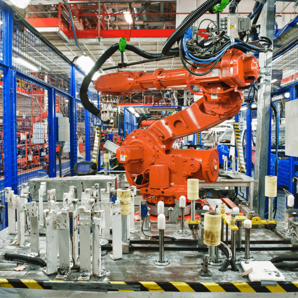


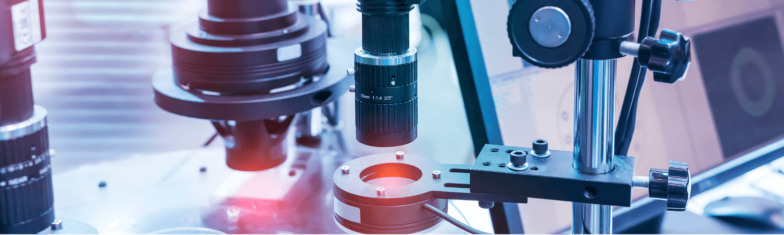

Machine vision systems represent a seamlessly integrated set of components meticulously designed to harness information extracted from digital images. Their primary purpose is to autonomously guide manufacturing and production operations, overseeing critical processes such as go/no-go testing and quality control. These intelligent systems leverage a combination of cameras, sensors, and sophisticated image processing software, enabling machines to visually interpret their surroundings and make informed decisions based on the captured images.
Industries across the spectrum, from automotive to electronics, food and beverage, pharmaceuticals, and beyond, benefit from the transformative capabilities of machine vision systems. Their versatility allows for a wide array of applications, including product defect inspection, precise dimensional measurements, and the verification of correct product assembly. Additionally, these systems play a crucial role in tracking products throughout the manufacturing process, ensuring accurate labelling and packaging.
Machine vision systems can be categorized into two main types: 2D and 3D. 2D machine vision systems specialize in capturing images of flat objects, providing valuable insights into surface details and characteristics. On the other hand, 3D machine vision systems are tailored to capture images of objects with depth, offering a more comprehensive understanding of the spatial aspects of the subjects being analysed.
Components of Machine Vision Systems
Machine vision systems typically consist of five fundamental elements, outlined below. While these components are widely used and can be found in various systems, their synergy and effective collaboration enable the creation of a sophisticated vision system capable of performing advanced functions.
1.Lighting and Machine Vision Systems:
Lighting plays a crucial role in illuminating objects and accentuating their distinctive features for camera observation. It stands as a pivotal component of machine vision systems since a camera is only effective in inspecting objects that are properly illuminated. Consequently, optimizing lighting parameters, including the distance of the light source from the camera and the object, as well as the angle, intensity, brightness, shape, size, and color of the lighting, becomes essential to highlight the specific features under inspection. Moreover, the camera must clearly capture the object when illuminated, necessitating consideration of the object’s surface properties during the optimization of lighting conditions. Various light sources, including LED, quartz halogen, fluorescent, and xenon strobe, can supply illumination. This lighting can be directional or diffusive. Machine vision systems categorize lighting techniques as follows:
2.Back Lighting:
Backlighting involves illuminating the subject from the rear, generating a distinctive contrast where dark outlines emerge against a well-lit background. This technique proves effective in identifying holes, gaps, cracks, bubbles, and scratches on transparent components. Backlighting is particularly well-suited for tasks such as measurement, placement, and positioning of parts. For exceptionally precise (subpixel) edge detection, it is recommended to employ monochrome light alongside controlled polarization.
3.Diffuse Lighting:
Diffuse lighting, also known as full-bright lighting, serves to illuminate glossy specular and mixed reflective targets, necessitating uniform and multi-directional illumination. There are three distinct types of diffuse lighting techniques:
4.Dome Diffuse Lighting:
This technique, widely employed, is particularly effective on curved and specular surfaces. Its primary advantage lies in minimizing glare, enhancing the overall visibility and detail of the target.
5.On-axis Lighting (Co-axial Lighting):
On-axis lighting utilizes a mirror to redirect light rays co-axially towards the target, aligning with both the target and the camera. This method is proficient at highlighting angled, textured, or topographical features on flat surfaces, especially those at an angle with the camera.

Types of Machine Vision Cameras
Here are the various categories of machine vision cameras:
Line Scan Camera:
A line-scan camera efficiently acquires digital images by capturing one line at a time with precision and speed. Although the camera observes the entire object, the software constructs the complete image pixel by pixel, requiring either the part or the camera to be in motion during inspection.
These cameras excel in inspecting multiple objects within a single line, making them well-suited for high-speed conveyor systems and continuous processes. They prove effective in examining continuous material webs like paper, metal, and textiles, as well as large parts and cylinders.
Area Scan Camera:
Rectangular image sensors are employed by area scan cameras to capture images within a single frame. The digital image produced is characterized by its height and width.
determined by the pixel count on the sensor. The vision processing unit systematically analyses the scene on an image-by-image basis. Area scan cameras excel at a wide range of common industrial tasks and boast ease of setup and alignment. In contrast to line scan cameras, area scan cameras are the preferred choice for inspecting stationary objects. These objects can be momentarily paused in front of area scan cameras to facilitate thorough inspection.
3D Scan Camera:
3D scanning cameras have the capability to conduct inspections across the X, Y, and Z planes, enabling the calculation of an object’s position and orientation in space. These cameras employ either a single or multiple cameras along with laser displacement sensors. In a setup with a single camera, the camera needs to be moved to create a heightmap based on the displacement of lasers on the object. The object’s height and surface planarity can then be determined using a calibrated offset laser. On the other hand, in a multi-camera configuration, laser triangulation is employed to generate a digitized model depicting the object’s shape and location.
These 3D scan cameras are well-suited for examining 3D-formed components and applications involving robotic guidance. They exhibit resilience to minor environmental disturbances such as variations in light, contrast, and colour while delivering precise information. Consequently, they find extensive use in metrology, factory automation, and the analysis of part defects.
Optical Comparator vs Machine Vision System
Optical comparators and machine vision systems are often misconceived as identical machines performing the same function, and while there is some truth to this assumption, they diverge in their operational processes. Both systems utilize a vision system to inspect parts, assessing accuracy and quality by capturing an image of a component and comparing it to a predefined representation.
The simplicity of the optical comparator’s design facilitates easy operation with minimal training. However, its manual placement of parts for calculations and observations contributes to a slower process. Consequently, optical comparators fall short in matching the speed, precision, and tolerances achieved by modern production methods. This inadequacy has fueled the ascendancy of machine vision systems.
Hyperspectral Imaging
Hyperspectral imaging distinguishes itself from other spectral imaging techniques by employing a greater variety of wavelengths and an increased number of spectral imaging techniques, enabling the collection of data pixel by pixel. Unlike a typical spectral imager that identifies red, green, blue, and near-infrared colours, a hyperspectral imager can discern hundreds of colours. This expanded capability allows hyperspectral machine vision systems to not only detect surface deformities or inaccuracies but also identify differences and impurities within an object.
Pre-programming the vision processing unit to identify specific targets, prompting the computer to search for registered targets within the image.
Employing colour differentiation analysis for more precise and accurate assessments.

Practical Positioning
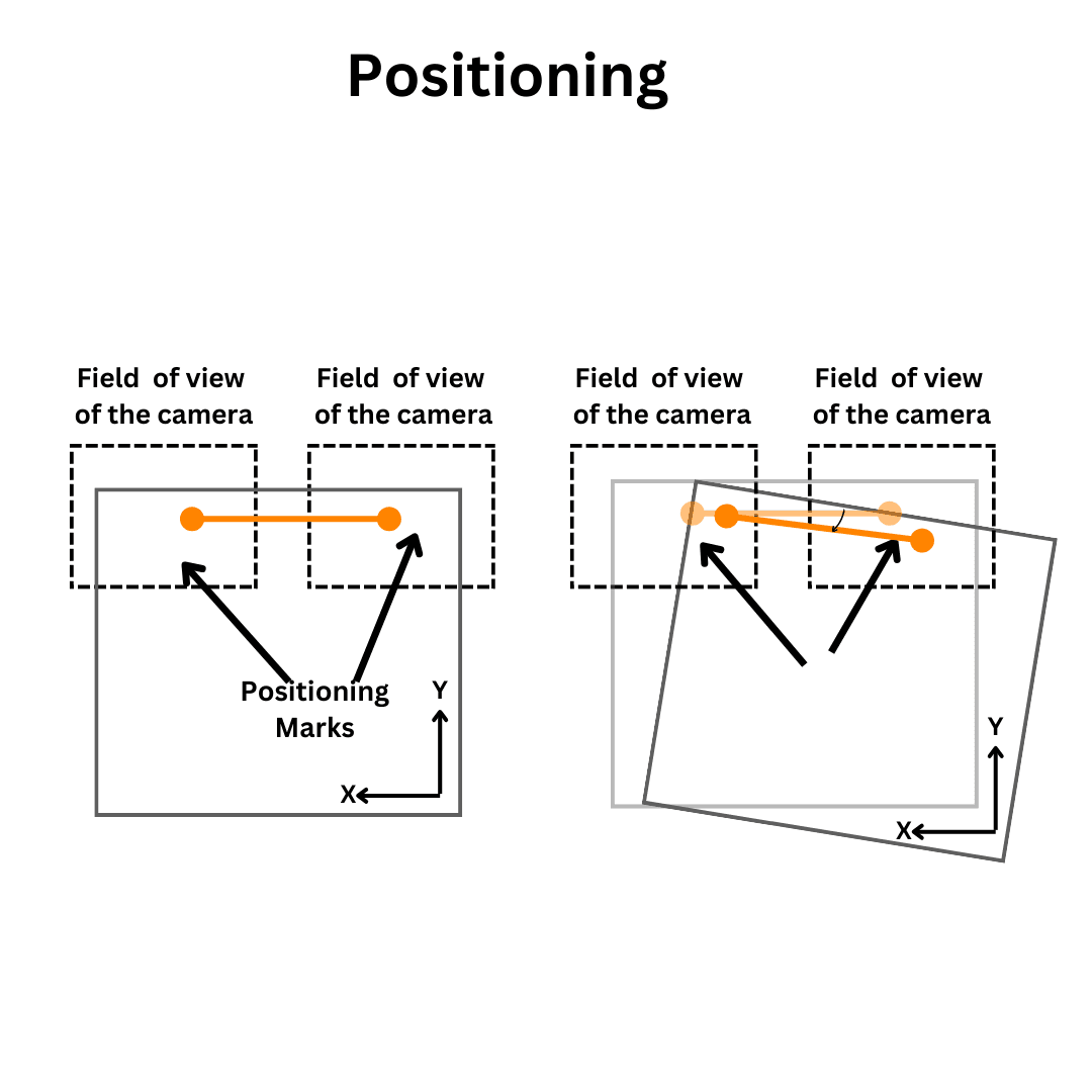
Positioning involves assessing the position and alignment of a component in relation to predetermined spatial tolerances. The specified location and orientation of the component in either 2D or 3D space are conveyed to a robot or machine element, enabling it to accurately position or align the target according to specified parameters. Machine vision positioning systems outperform manual methods in terms of precision and speed, particularly in tasks such as robotic handling of parts on and off conveyor belts, aligning glass substrates, verifying barcode and label alignment, inspecting IC placement on PCBs, and organizing parts within a pallet.
Machine Vision Identification
Machine vision identification involves scanning and interpreting barcodes, 2D codes, direct part marks, and printed characters on parts, labels, and packages. These markings typically include information such as product name, manufacturer details, date code, lot number, and expiration date. This identification process is valuable for enhancing part traceability, managing inventory, and ensuring product verification. It can be achieved through either optical character recognition (OCR) or optical character verification (OCV) systems. OCR systems read alphanumeric characters on the target without prior knowledge of the specific characters, while OCV systems verify the presence of the character strings.
Flaw Detection:
Detecting flaws stands as a critical quality control task within manufacturing industries and represents the most extensively employed function of machine vision systems. In this process, the machine vision system scrutinizes part surfaces for defects such as cracks, scratches, blemishes, gaps, contaminants, discoloration, and other irregularities that could impact product functionality and reliability. Given the random occurrence of these defects, the machine vision algorithm actively seeks pattern alterations, changes in color or texture, discontinuities, or connected structures. Subsequently, the system monitors the presence of these defects and categorizes them based on type, colour, texture, and size, effectively identifying and segregating defective parts that fail to meet specified criteria. Notably, machine vision systems excel in swiftly and accurately detecting small and microscopic flaws that may escape the human eye, and they can operate continuously for extended periods, unlike human inspectors.
Flaw detection finds widespread application in inspecting semiconductor and electronic components, appliances, tooling conditions, food products and their packaging, and materials produced in continuous webs such as paper, plastics, and metals. It proves particularly valuable in online inspections, where the identification of a faulty part prompts an immediate halt to the manufacturing process for correction, and the defective part is separated from the lot. Typically integrated into machine vision systems alongside functions like presence inspection, measurement, and positioning, flaw detection enhances overall quality control in diverse industrial settings.
Detecting Through Measurement :
Measurement involves assessing the dimensional accuracy and geometric tolerances of components. In machine vision systems, the distances between multiple points and the positions of targeted features on an object are computed to ascertain compliance with specifications. To achieve highly accurate, precise, and consistent measurements, the lighting and optical system of the machine vision system must be optimized.
Applications of Machine Vision Systems
Machine vision systems have countless practical applications. The industry-specific applications of these systems are the following:
Food, Pharmaceutical, and Consumer Products
1. Packaging and identifying food, beverage, pharmaceutical, and consumer products require a reliable and robust inspection system.
2. The machine vision guides the robotic arm in the pick-up and placement of products in boxes. The system counts the number of products contained in each box before sealing.
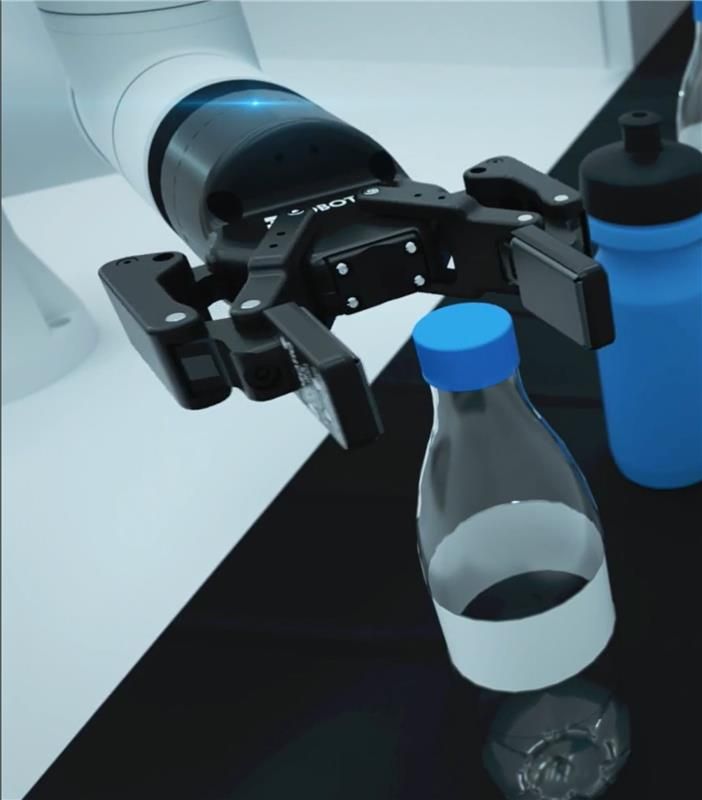
3. Cans, bottles, and caps are inspected for defects such as cracks and dents.
4. Instant noodles are checked for the presence or absence of seasoning packets. This type of inspection is also applicable to products containing several kinds of items.
5. Bottles and sachets of liquid products are inspected in liquid dispensing lines if properly filled.
Semiconductor Quality Control
Detecting and locating flaws play a crucial role in ensuring the quality of semiconductors, making machine vision systems invaluable in the semiconductor industry.
The integrity of integrated circuits (IC) and their solder joints on printed circuit boards (PCBs) is susceptible to cracks and voids, which can significantly impact functionality and reliability. Inspection of IC leads includes checking for bending and coplanarity, while the positions of balls in ball grid array (BGA) packages are meticulously examined. Before mounting on the PCB, the orientation and alignment of ICs and other electronic components undergo thorough scrutiny.
Automotive and the Machine Vision System
A robotic arm, guided by a machine vision system, conducts the assembly and handling of automotive components. The spark plugs dimensions undergo verification, while flaw detection is employed for inspecting various components such as differential gears, engine valve heads, piston side coatings, oil seals, diesel particulate filters, and more.
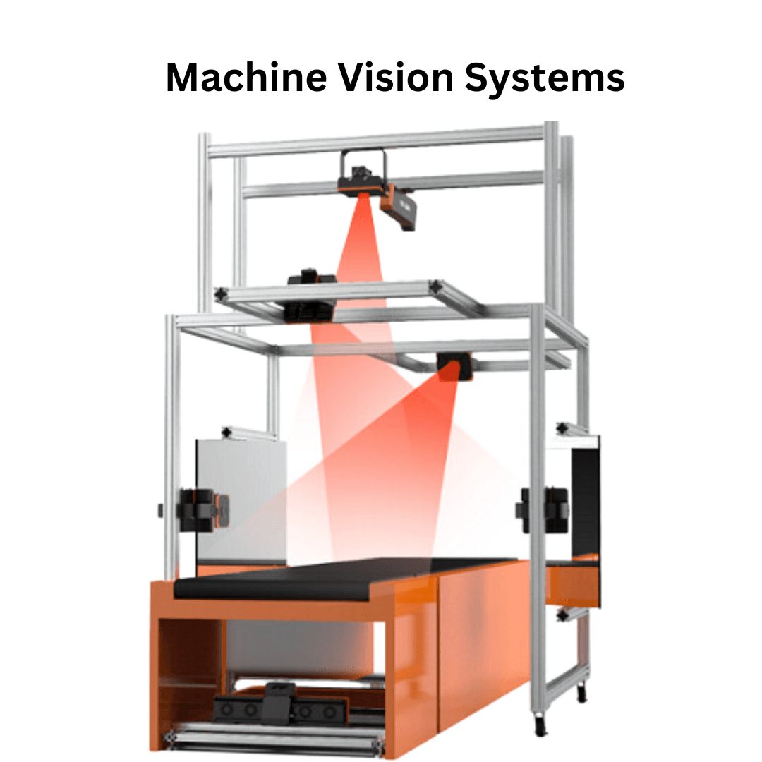
Machine Vision System Design
Designing a machine vision system involves addressing the complexities of integrating diverse components and subsystems, orchestrating them to operate seamlessly as a cohesive and efficient unit. The first steps in this endeavour entail defining the system’s functionality and operational parameters.
Every facet of the design project undergoes thorough assessment and specification to ensure that the machine vision elements, components, and concepts align with the intended requirements and goals of the application.
Selection of the Camera
The term “camera” pertains to the image acquisition component within a machine vision system. The criteria for selection involve feature detection, identification, location, or measurement, along with considerations for the processing speed. Once the criteria are established, one can determine the spatial resolution, image resolution, and framing rate suitable for the specific application
Spatial Resolution
Spatial resolution denotes the number of pixels required for processing the smallest feature or achieving the necessary precision and repeatability. Very minute features, such as holes or bolts, may demand only a few pixels, but this may compromise reliability. Enhancing resolution necessitates an increase in the number of pixels to improve spatial resolution.
When considering both size and measurement, both types of spatial resolution become crucial, with the smaller one often proving to be the optimal selection.
Image Resolution
Image resolution refers to the columns and rows required to achieve the appropriate spatial resolution. Calculating image resolution involves dividing the image area by spatial resolution, determining the number of pixels needed in width and height. For optimal results, the camera should possess a row and column count surpassing the quotient from this division.
Imaging Rate
The final step in camera selection involves determining the required frames per second for the application. Typically, most machine vision systems operate at 10 to 15 frames per second or slower. Higher resolutions necessitate a slower image rate.
Lens Selection
The lens selection process considers format, field of view, distance from components, and optical resolution. Calculations include optical resolution, magnification, and the focal length of the lens.
Lens Format
Lenses are designed for specific sensor sizes, formatted to match the lens’s circle size. It’s crucial to match the lens format to the sensor format. C mounts are used for low to medium resolution sensors, with mounting determined by camera and sensor sizes.
In Conclusion
Machine vision systems are transforming industries by offering precise, effective, and automated solutions for activities like positioning, quality control, and inspection. These systems use cutting-edge parts, including as cameras, lights, and software, to provide accurate insights and improve operational efficiency in a variety of industries, including electronics, food, medicines, and automobiles. Machine vision systems guarantee superior flaw identification, product verification, and measurement accuracy by utilizing 2D, 3D, and hyperspectral imaging technologies. Machine vision systems are positioned to become increasingly more important in streamlining production procedures, enhancing product quality, and boosting productivity in a variety of industries as the need for automated solutions keeps growing.