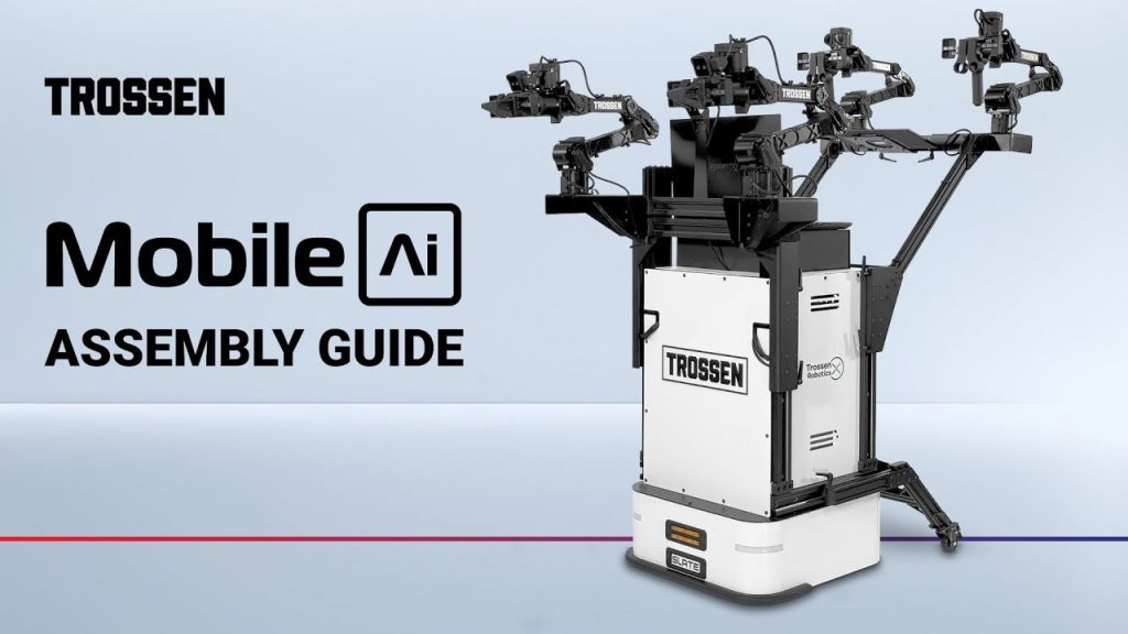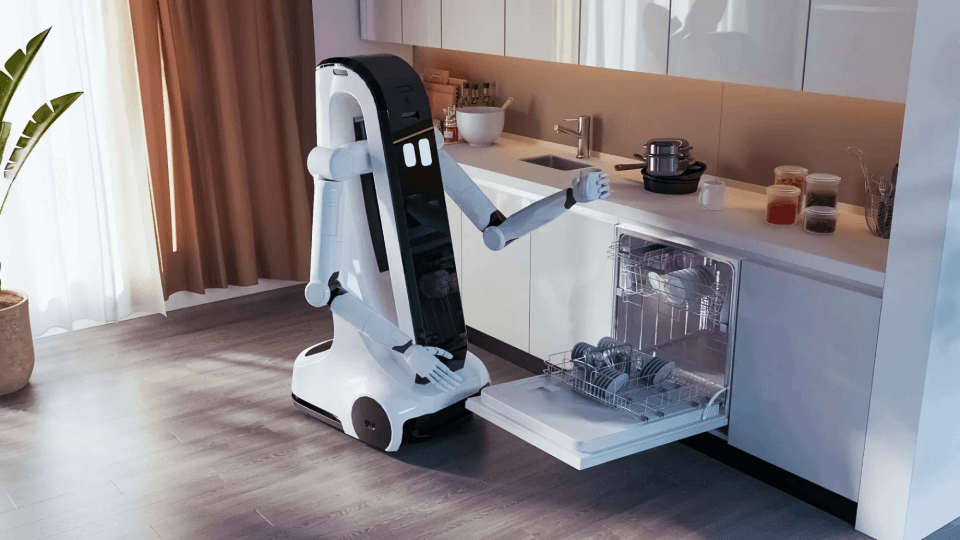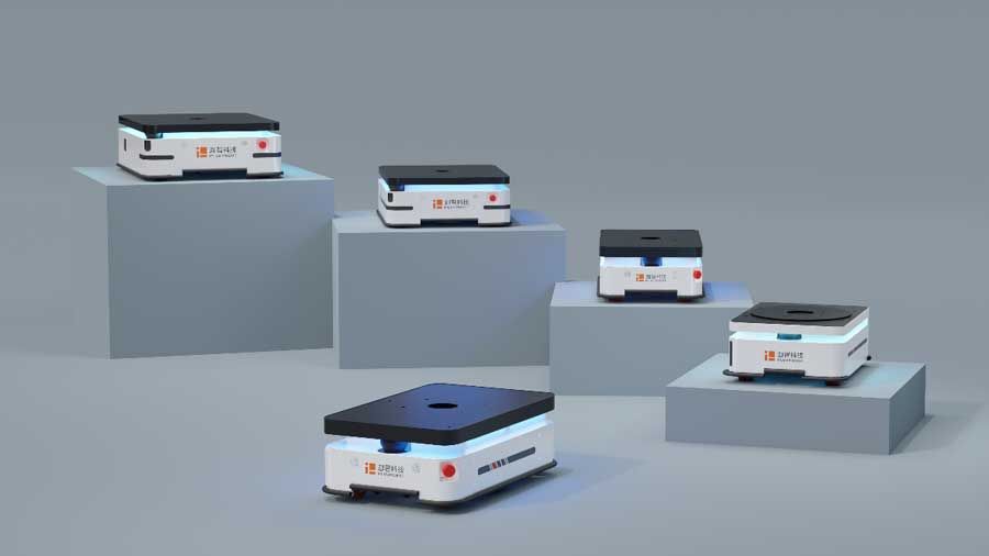




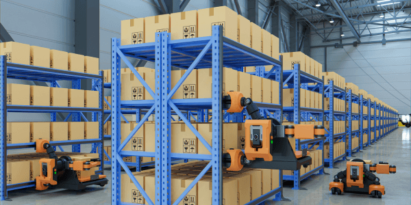
The fusion of AGVs and robotic arms yields a dynamic mobile platform capable of executing a myriad of tasks, ranging from remote handling and telemanipulation to scanning and probing. AGVs find application across diverse domains including manufacturing , warehousing, inspection, exploration, transportation, and military operations.
Types and Industrial Applications of AGVs
1. Forklift AGV: AGVs primarily find application in logistics, with functions like exploration, inspection, and service robotics representing a smaller segment of the industry. Consequently, automated guided vehicles are classified based on their load capacity and transportation method.
2. Underride AGVs: AGVs also known as automated guided carts (AGCs), are a specific type of AGV designed to lift a load by manoeuvring beneath a basket or cart and lifting it slightly. These AGVs are capable of autonomously orienting and depositing the load at its destination without requiring manual intervention. Primarily employed in hospital settings, they serve the purpose of delivering food, linens, and medical supplies efficiently.
3. Towing AGV: Towing or tugger automated guided vehicles are tasked with pulling undriven carriers or trailers. Unlike forklifts and underride AGVs, their load-handling process doesn’t require lifting, enabling them to manage multiple loads simultaneously. However, they are limited to transportation tasks and cannot position the loads at their designated locations.
4. Unit Load AGVs: Are engineered for the transportation of unitized or palletized goods. Unlike other types, they do not lift loads off the floor, necessitating the use of additional lifting equipment like conveyors, cranes, or forklifts for loading and unloading purposes.
5. Assembly AGVs: Also known as tunnelling AGVs, serve the purpose of transporting goods to assembly processes. Given the controlled nature of assembly environments, navigation for assembly AGVs is simplified compared to other types, with lower driving speeds. They boast high manoeuvrability, enabling them to seamlessly fit into and orient within assembly stations.
Tunnelling AGVs operate by pulling a companion frame to a designated drop-off location. Upon arrival, they may traverse over an RFID puck, which triggers the AGV’s next stop. Compared to forklift AGVs, assembly AGVs offer greater efficiency and cost-effectiveness as they only necessitate a companion frame for the delivery of assembly parts or components.
6. Heavy Load AGVs: Find extensive application in industries like paper and steel mills, where they are employed for the transportation of bulky rolls of finished products destined for storage or distribution. Distinguished by their sturdier construction compared to other variants, they are outfitted with additional safety features to ensure secure handling of heavy loads.
7. AGV Scissor Lifts: AGV Scissor Lifts present an ergonomic solution for positioning large products during assembly tasks. Upon reaching a workstation, the product is effortlessly raised or lowered, eliminating the need for workers to strain or bend during the assembly process. Capable of lifting loads weighing up to one or two tons to heights of up to 50 inches, AGV scissor lifts ensure convenient and accessible working conditions.
8. Truck Loading AGVs: Also known as automated trailer loading (ATL) AGVs, offer a distinctive approach to truck loading and unloading operations by eliminating the need for traditional guidance systems. These AGVs can seamlessly load and unload trucks without requiring any modifications to the truck’s trailer or the dock. They possess the capability to handle pallets or unit loads in various load patterns, including mixed orientations, and can traverse over dock plates and uneven surfaces while carrying loads of up to four pallets.

The AGV Navigation System
Navigation encompasses the capability of a guided vehicle or mobile robot to ascertain its location and autonomously chart its course while circumventing collisions and unsafe environments. Navigation comprises four key components: perception, localization, path planning, and motion control.
Perception of Surroundings
The process of gathering data for mobile robot navigation is broader and more intricate compared to that for robotic arms. Similar to robotic arms, mobile robots rely on sensors for perception. However, their heightened sophistication lies in their ability to globally measure and interpret their position or surroundings over an extensive range.
Classification of Sensors
Sensors are categorized based on two functional axes: Proprioceptive/exteroceptive sensors and passive/active sensors. These classifications delineate sensors by their monitoring functions and their interaction with the environment.
1. Proprioceptive sensors: Gauge internal parameters such as battery levels, wheel position, motor speed, load, temperature, and current. Examples include encoders, potentiometers, gyroscopes, and compasses.
2. Exteroceptive sensors: Observe environmental aspects like distances, electromagnetic wave intensity, and acoustic amplitude. Common types include sonar, IR-sensitive sensors, and ultrasonic distance sensors.
3. Passive sensors: Utilize devices such as temperature probes, microphones, and cameras to survey the environment and absorb energy like loads, electromagnetic waves, or vibrations.
4. Active sensors: Emit energy into the environment and analyze the resulting reaction. For instance, an active sensor like sonar transmits an acoustic wave, and the echo is then analyzed and measured for information.
5. Tactile Sensors: Tactile sensors, including contact switches and proximity sensors, operate by mechanical measurement. They detect physical contact, as seen in limit switches, or utilize other physical phenomena such as magnetism (e.g., reed and Hall effect switches) and electric induction (inductive switches).
6. Heading Sensors: Heading sensors, such as compasses and gyroscopes, serve to ascertain the orientation of the robot concerning a fixed, external reference point or frame.
7. Wheel and Motor Sensors: Wheel and motor sensors gauge the angular position, speed, and acceleration of a motor or wheel. For instance, an encoder embedded in a servo motor provides feedback signals utilized to regulate the motor drive.
Localization and Orientation
Following the acquisition of environmental data or from a fixed reference frame, the robot processes this information to ascertain its position and orientation relative to the environment, a process known as localization. Position and orientation can be determined via methods such as odometry (dead reckoning) or triangulation from fixed reference frames. However, these methods may fall short, particularly in scenarios requiring high accuracy.
Path Planning
Path planning involves determining the sequence of actions required for the robot to reach its destination. This cognitive process entails analyzing the environment map and generating output in the form of a program or set of instructions. If any attributes within the map change, the robot must be capable of detecting these alterations and adapting its actions accordingly. Furthermore, the robot not only identifies the route to its target location but also optimizes its path by minimizing the distance travelled while avoiding obstacles.
Path Planning Path planning involves describing four key concepts: The robot’s geometry, the degrees of freedom of its effectors, the map of the environment, and the initial and target configurations. These concepts are translated into what is known as the configuration space to solve the robot’s path planning. In this space, the possible configurations of the robot and the space occupied by obstacles are represented. The robot is simplified to a point defined by coordinate vectors in the configuration space, with obstacles somewhat inflated to account for the robot’s size. By understanding the possible configurations of all objects on the map, a continuous curve or path corresponding to a robot’s trajectory can be determined.
Motion Control
Motion control refers to the robot’s ability to execute its planned or programmed sequence of actions by providing input signals to its drivers, actuators, and effectors. In the case of mobile robots, the control system typically operates as a closed loop. The most commonly used closed-loop control in robotics is Proportional-Integral-Derivative (PID) control, a form of feedback control. Feedback control enables the robot to correct any disturbances or errors in its trajectory by continuously measuring parameters internally and externally. A PID controller mathematically represents the error signal and adjusts the proportional, integral, and derivative gains to quickly eliminate errors while maintaining stability and avoiding overshoot.
1. Zone Blocking: Zone blocking is managed by a centralized AGV system controller, allowing only one AGV to enter any specific zone at a time. This method is implemented in segments of the guide path featuring intersections, stations, and turns. It enables the simultaneous release of multiple vehicles into high-traffic intersections while preventing interference between them.
2. Accumulative Blocking: Accumulative blocking operates without a centralized system control but relies on remote object detection sensors. It is employed in long, straight sections of guide paths where AGVs detect the approach of slower or stationary AGVs along the path. AGVs in accumulative blocking tend to accumulate behind one another but proceed to the next intersection as space becomes available. This process is characterized by higher speed and efficiency compared to zone blocking.
Systems
The entire navigation system is developed by integrating the processes of perception, localization, path planning, and motion control. Furthermore, various types of navigation systems can be crafted by combining sensors, controllers, programs, and algorithms. Presented below are the most utilized navigation systems for automated guided vehicles (AGVs).
1. Physical Guides
Physical guides encompass guide tracks, tapes, and wires, which are detected either actively or passively. This navigation system relies on fixed reference points or environmental landmarks, which are sensed and evaluated by sensors and controllers. As AGVs follow predetermined paths for navigation, the path planning process can be preprogrammed into their systems.
For instance, the inductive guide track, or wire guidance system, consists of a current-carrying conductor embedded into the ground or floor. The track is divided into segments that can be switched on or off to sectionalize the tracks. An alternating current flow through the wire, generating electromagnetic waves detectable by sensors mounted at the bottom of the AGV. These sensors typically comprise two coils through which induced currents produce analogy signals fed to the feedback controller.
2. Anchoring Points
Anchoring points serve as physical guides for free navigation. Unlike traditional wire and tape installations, anchoring points utilize a grid of permanent magnets (magnetic bars) or transponders placed on the floor to establish the location and orientation of the automated guided vehicle (AGV). Like the magnetic strip guide, magnetic proximity sensors are mounted on the underside of the AGV. The robot’s path is determined through pre-programming or path planning based on the signals received from these anchoring points.
3, Laser Navigation
Laser navigation employs active-ranging light sensors for localization, enabling free navigation within the environment. Markers, such as reflective foils or tapes, are affixed to walls or objects and can be readily detected by the laser sensor. Triangulation is achieved with a minimum of three markers, facilitating accurate localization. As the automated guided vehicle handles localization and path planning, its trajectory is highly flexible. Additionally, the system can compute the optimal path for navigation.
4. Global Positioning System (GPS)
GPS navigation is primarily employed in outdoor environments where installing artificial markers is impractical. Utilizing GPS satellites as beacons, data is transmitted to the AGV to triangulate its position. However, relying solely on GPS has limitations due to its lower accuracy, particularly indoors. To ensure a consistent and reliable signal, there must be an unobstructed line of sight between the satellite and the automated guided vehicle.
5. Wireless Connectivity for AGV Navigation
The growing prominence of AGV systems underscores the importance of robust connectivity systems to ensure swift and efficient operation. Designing and planning a wireless connectivity system necessitates careful consideration of several factors to achieve optimal reliability.
(a) Reliability: In manufacturing environments, electrical interference such as ground loops and conveyor belts can disrupt AGV performance. Moreover, vibrations from AGV operation may interfere with its functionality. Wireless navigation systems must be fortified with radio frequency (RF) and power isolation to safeguard against electrostatic discharge damage and inrush from motor currents. These protective measures not only ensure dependable service but also enhance the longevity of AGVs in harsh and electrically active settings.
(b) Continuous Operation: AGVs constantly seek and switch to access points with stronger signals, requiring an environment conducive to smooth roaming transitions and seamless connectivity. Wi-Fi coverage dictates the speed at which AGVs locate access points, underscoring the necessity for wireless devices equipped with multiple input and multiple output (MIMO) capabilities to minimize the need for additional access points. Identifying the appropriate wireless local area network (WLAN) settings and employing external antennas on AGVs to broaden Wi-Fi coverage are crucial steps for successful integration.
Despite precautions, environmental obstacles such as walls, pillars, or large equipment may still cause interference, hindering access point detection and potentially leading to collisions. Implementing a request-to-send and clear-to-send (RTS/CTS) mechanism can mitigate such risks and prevent collisions.
(c) Security Software: Securing the wireless network with robust security protocols is imperative to prevent unauthorized access and system shutdowns. All wireless communication devices should be protected to ensure access only by authorized personnel. Management software capable of monitoring the network environment and controlling access to connections plays a pivotal role in maintaining network security and integrity.
AGV Locomotion
Locomotion refers to the ability of automated guided vehicles (AGVs) to move from one point to another. Wheels are a common mode of locomotion due to their simplicity and minimal friction loss. However, wheeled AGVs may face limitations in environments with irregular or uneven surfaces, leading to a preference for legged robots in such scenarios.
1. Wheeled AGVs: Wheels are favored for their high efficiency and straightforward mechanical implementation. They offer a wide degree of freedom, high stability, and excellent maneuverability. In robotics, wheels are categorized based on their kinematics. The various types of wheels used in AGVs include:
2. Standard Wheel: ,A standard wheel provides two degrees of freedom: rotation around the wheel axle and around the contact point. The axis of rotation around the contact point typically passes through the wheel’s centre, aligned with the plane of the wheel. This design facilitates steering without introducing additional forces to the robot chassis, assuming the wheels are aligned with no camber and toe.
3. Caster Wheel: Like the standard wheel, a caster wheel provides two degrees of freedom: rotation around the wheel axis and rotation around an offset from the wheel’s centre. Caster wheels are primarily employed to support the chassis. While they are seldom used for maneuvering and generating motion due to the forces exerted on the chassis during steering, caster wheels offer the advantage of automatic alignment when moving forward after a turn.
4. Meconium Wheel: Also known as Swedish wheels, a Meconium wheel possesses three degrees of freedom: rotation around the wheel axis, rotation around the rollers, and rotation around the contact point. It features rollers positioned along the circumference of the main wheel at 45° angles, although another configuration involves rollers oriented at 90° angles, forming an omnidirectional wheel. To enable omnidirectional movement, three or more Meconium wheels are installed on the chassis and rotated both clockwise and counterclockwise.
5. Ball or Spherical Wheel: A spherical wheel provides three degrees of freedom, enabling rotation around all three axes. However, true spherical wheels are largely conceptual due to challenges when implementing them into large chassis. Issues such as opposing rotation between drivers, unpowered stability, and difficulties in power transmission with the drive system arise.